The working principles
|
|
|
The Stirling engine is a high-efficiency heat engine invented by Reverend Robert Sterling of Edinburgh of Scotland in 1816. Even though it is not a new invention, there have been at least thousands of different designs stemmed from his original patent.
The
Stirling engine is an external-combustion engine compatible with any
high-temperature external heat sources such as solar energy, waste heat, nuclear
energy, natural gas, and any fuel. This is different from the
internal-combustion engines such as gasoline engines and diesel engines.
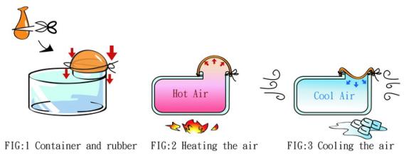
A1. Air Properties
As shown in FIG. 1, tie the rubber on the container opening. It is easy to understand that the rubber expands when heated (FIG. 2), and contracts when cooled down (FIG. 3), this is because the internal air pressure acts upon the rubber (FIG. 2), and of course the air pressure cannot be seen by the human eye.
![]()
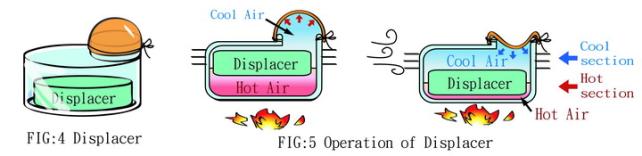
If a displacer is put into the container (FIG. 4) and the displacer diameter is a little bit smaller than the container’s inner diameter, the gas in the container can be pushed down-and-up when the displacer is moved freely up-and-down. Meanwhile, if the container bottom is heated and the container top is cooled with enough temperature difference between the top and bottom ends, the rubber will continuously expand and contract. The principle is as follows:
When the displacer moves upward, the gas inside the container is pushed to the container bottom, meanwhile the container bottom is heated so that the gas is heated and the gas pressure is increased, the pressure passes via the gap between the piston and the container to the rubber, making the rubber expand (FIG. 5).
On the contrary, if proper force is applied to move the displacer downward, the gas inside the container is pushed to the container top, meanwhile the container top is the cool section and the gas is cooled to lower the gas temperature and pressure, thus the rubber contracts (FIG. 5).
Thereby, the displacer continuously moves freely up and down and the rubber expands and contracts continuously.
Therefore, the main function of the displacer is to move gas and make the gas flow between the cool and hot ends.
You only need to connect the displacer with a crank (FIG. 6), and the displacer can move up and down. When the crank rotates, the displacer is driven up and down. When the connection of the displacer and the crank is done, heat the container bottom and cool the container top, use your hand to rotate the crank to move the displacer up and down first, then the rubber expands and contacts repeatedly (FIG. 7).
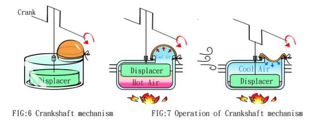
The expansion and contraction of the rubber can be transformed into power output and the function of the rubber is the same as a power piston. A linkage can be connected to the above-mentioned crank and then the movement of rubber expansion and contraction are transformed into the rotation of crank. The crank section connected to the displacer and that connected to the power piston need to have a fixed phase angle, generally 90 degrees (FIG. 8 and 9). The crank rotation produced by the rubber expansion can contract to provide the force needed by the displacer to move up and down, and extra force can be outputted. It is noted that the displacer does not move by itself and is driven by the crank, and the power source is the power piston.
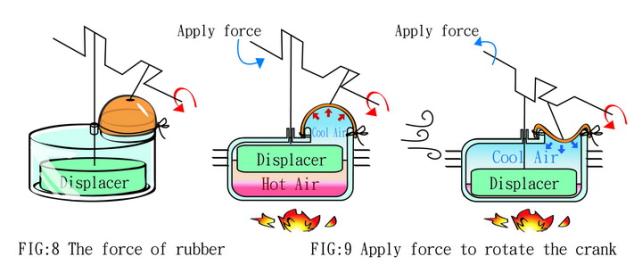
As shown in FIG. 9, when the displacer moves to the top position, the bottom space for heating is the largest, and meanwhile the pressure generated is the largest. When the displacer moves to the bottom position, the top space to be cooled is the largest, and the pressure generated is the smallest. If connecting the crankshaft of the power piston to the farthest position of crank level position, the biggest twisting force can be generated, and meanwhile the crank section connected to the displacer and that connected to the power piston have an angle difference of 90 degrees, which is called the phase angle.
The above conditions are results of operation in static environments. Typically, the phase angle is set to be 90 degrees. When the rotating speed of engine, load, temperature, and gas used are different, the optimal phase angle may be different.
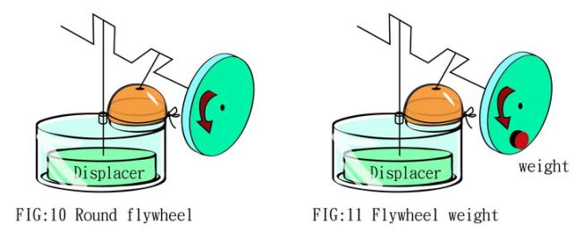
The above parts are not enough to operate the engine because the expansion and contraction of the rubber (FIG. 8, 9) can not make the crank rotate for a complete cycle. Therefore, a flywheel of high rotational inertia must be added. The flywheel used here is a circular flywheel, as shown in FIG. 10. In addition to the need in inertia, when balance or a change in the inertia is concerned, another weight may be attached on the flywheel (FIG. 11).
B. Advanced
The Stirling engine is a high-efficiency energy transformer using the closed gas cycle and regenerator design. In theory, the thermal efficiency of the Stirling engine is the same as that of a Carnot engine, and both belong to reversible cycle with the highest thermal cycle transforming efficiency. The gas used in a Stirling engine can be high-pressure air, nitrogen, helium or hydrogen. Generally, there are two possible dispositions: the first one is using a power piston to compress or expand the gas, and using a displacer to make the working gas flow back and forth in the cylinder; the other one does not use the displacer and using two pistons to achieve the purposes of compressing and expanding the gas and pushing the gas back and forth. When the gas in the cylinder is pushed to the heated section to absorb heat, the expansion pushes the power piston and power is outputted.
Stirling engines can be divided
into four types according to the number of cylinders, power pistons and the
arrangement of displacer:
(1)
α
type — twin-cylinder Stirling engine, this type dose not have a displacer but
has two power pistons working separately in two independent
cylinders.
(2)
β
type — coaxial piston-displacer Stirling engine, has one power piston and a
displacer both in the same cylinder and move along the same axis. Free-piston
type Stirling engine belongs to this type.
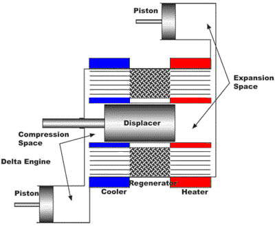
(3) γ type — two independent cylinders, one of them is disposed with power piton while the other is disposed with a displacer.
(4)
δ
type — three independent cylinders, this type have a displacer
and has two power pistons working separately in three independent
cylinders.
 (ref.
Tomsidpeat
Web information)
(ref.
Tomsidpeat
Web information)
The Stirling engine has high efficiency at different rated powers, and is an external-combustion engine with heating from ambient pressure combustion. Therefore the combustion is complete and the exhaust is cleaner. Most of all, it can use different heat sources including gasoline, natural gas, solar energy, biomass power and waste heat. In recent years, researchers related to energy engineering pay increasing attention to the development of the system. This makes the Stirling engine one of the possible power sources in the 21st century.
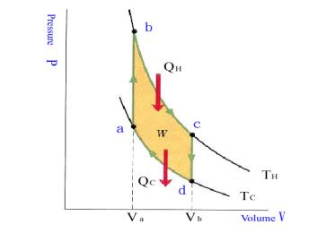
The above drawing describes basic concepts of thermal
cycle of an ideal Stirling engine:
(1) a→b process, working fluid absorbs heat and raise temperature with constant volume;
(2) b→c process, working fluid absorbs heat and expands at constant temperature;
(3) c→d process, working fluid cools and lower temperature with constant volume;
(4) d→a process, working fluid cools and contracts at constant temperature.
Comparing the Stirling engine with the Carnot engine, the former includes two isothermal processes and two constant-volume processes, while the latter includes two isothermal processes and two adiabatic processes. In other words, the Stirling engine cycle replaces the two adiabatic processes in the Carnot cycle with two constant-volume heat-absorbing and heat-dissipating processes. Therefore, if the Stirling engine cycle is to have the same thermal efficiency with the Carnot engine, the heat dissipated by the working fluid in process c→d must be used as regeneration heat to heat up the working fluid in process a→b. This process is called regeneration and the device is called regenerator.
It should be noted that actually the temperature and pressure of the working fluid inside the Stirling engine is not completely uniform during the cyclic operation. Therefore, the volume and pressure changes are not as distinct as that shown in the above figure.